Preamble 1pre · A 97
The SMA manual expressly describes operating modes displayed through LEDs on the inverter housing.
The recorded strength is A 97 for this element in both grounds. Coverage of this element does not resolve the separate single-LED question.
SMA BEN082220 · §4 · Printed p. 16
R1 · Original p. 16
Limitation 16a · A 95
The manual describes separate inputs with individual MPP trackers, per-input faults and per-string measurements.
The complete mapping uses several passages. The research record separately addresses the meaning of “input channel”.
SMA BEN082220 · Printed pp. 13, 23, 40, 44
R1 · Original p. 13 R1 · Original p. 23 R1 · Original p. 40 R1 · Original p. 44
Limitation 16b · A 97
SMA expressly connects the device’s operating mode with the integrated LEDs.
This passage supports actuation of the indicators. Whether the claimed states appear on one system-status LED is assessed separately.
SMA BEN082220 · §4 · Printed p. 16
R1 · Original p. 16
Limitation 16c1 · B 75
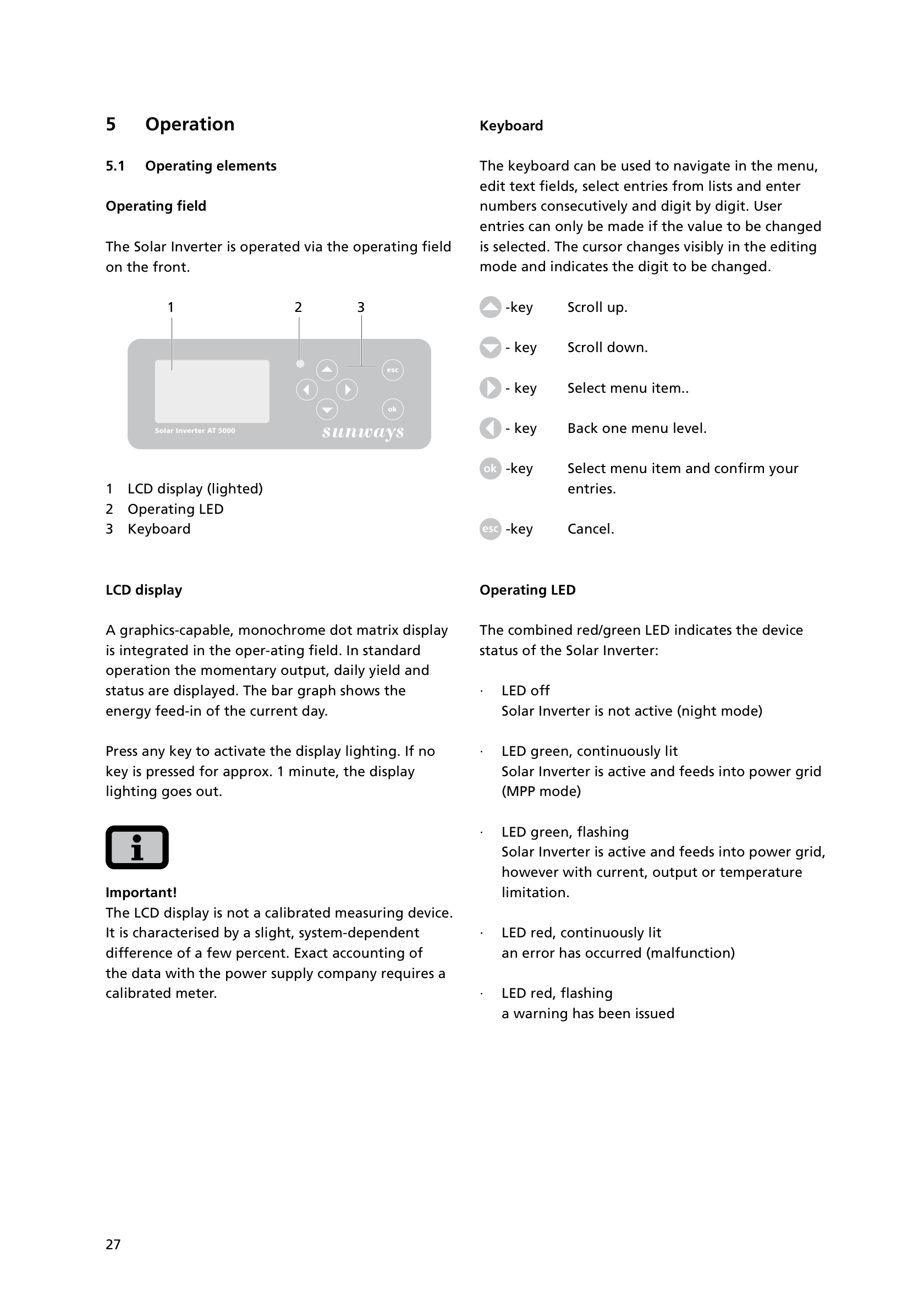
Sunways describes one combined red/green LED, continuously green during grid feeding. The chart combines that indication with SMA’s monitored-input architecture.
B 75 is the recorded strength of the combination, including its reason to combine. This source passage is one part of that ground.
Sunways AT manual · §5.1 · Printed p. 27
R4 · Original p. 27
Limitation 16c2 · C 50 · Weakest
The manual describes continued grid feeding with a current, output or temperature limitation. Its separate red-flashing state states a warning, but does not say whether feeding continues.
This mapping depends on treating the operating limitation as a warning, the manual’s date evidence, and the reason to combine references. That uncertainty remains visible.
Sunways AT manual · §5.1 · Printed p. 27
R4 · Original p. 27
Limitation 16c3 · B 75
The Sunways combined LED shows a continuously red error state. The chart also cites Fronius, Soladin and a Japanese reference for error indications.
The score includes the reason to combine these indications with SMA’s architecture. A single isolated passage is not the complete ground.
Sunways AT manual · §5.1 · Printed p. 27
R4 · Original p. 27
Limitation 16c4 · B 75
The Sunways display distinguishes an AC-network error. The chart relies on Soladin and the Japanese 366 publication for a grid-specific code on one LED.
The highlighted Sunways text describes a display code, not a distinct grid-error LED state. The other references supply that part of the combination.
Sunways AT manual · §5.5 · Printed p. 38
R4 · Original p. 38
Limitation 16c5 · B 75
Sunways identifies the unlit state as inactive night mode. The chart cites corresponding states in the Soladin and Fronius documents.
The recorded B 75 reflects the combined ground and its reason to combine, rather than this sentence alone.
Sunways AT manual · §5.1 · Printed p. 27
R4 · Original p. 27
Claim-wide point P2 · B 78
The recorded rationale addresses putting SMA’s monitored operating states onto a single two-colour indicator. It is a claim-wide point, not an additional limitation.
The assessment records a three-reference combination. This point affects the 16c1–16c5 ratings and must be read with the complete rationale.
Claim chart · Ground 2 · Combination rationale
R1 · Original p. 16 R4 · Original p. 27